Appendix: Discontinued FaxPress Products
About the FaxPress SBE
The discontinued FaxPress SBE server provides fax services for small to medium size networks with medium fax traffic. The FaxPress SBE unit has a single Motorola Cold Fire CPU5102, 8MB of RAM, 0.5 MB flash ROM, and two 14,400 kbps fax modems. Email Gateways to support fax and email integration are not included with the SBE.
About the FaxPress 7500 DID and E&M
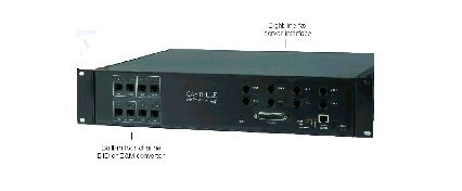
The FaxPress 7500 is a rack-mountable eight line fax server that includes either a built-in four channel DID (Direct Inward Dialing) or E&M (Ear & Mouth) converter module. The FaxPress 7500’s two sets of interface connections include the eight line fax server interface on the right, and the four channel DID or E&M conversion interface on the left.
All eight fax lines of your 7500 DID or 7500 E&M can be connected to regular telephone lines. Typically, however, four of the FaxPress’ eight fax lines are connected to the FaxPress’ built-in DID or E&M converter’s four channels for inbound faxing, and four are connected to regular phone lines for outgoing faxing.
FaxPress fax lines connected to DID and E&M converter channels support inbound faxing only. Faxes cannot be sent out through FaxPress lines connected to DID or E&M converter channels. To use FaxPress to send faxes as well as receive them, at least one of the FaxPress 7500’s eight fax lines must be connected to a regular phone line.
If you plan to use a T1 line with either the FaxPress 7500 DID or E&M systems, please contact Castelle technical support at 1-408-852-8080 for additional third party equipment and configuration requirements.
Using the FaxPress 7500 DID with your DID trunk will require both hardware setup, described in the following Before You Begin and Connecting the FaxPress 7500 DID to your DID trunk sections, as well as FaxPress server software configuration, described in Configuring the FaxPress 7500’s Server Software.
Before configuring the FaxPress for use with your DID trunk lines, please confirm:
| ■ | the FaxPress 8.x server software is installed. (See Installing the Server.) |
| ■ | the FaxPress Client for supervisors is installed. (See Installing FaxPress Clients.) |
| ■ | the FaxPress 7500 can send and receive test faxes through a standard phone line connected to any of the FaxPress’ eight fax lines. |
Also, with regard to your DID trunk line, please make sure:
| ■ | you have one or more DID trunk lines ready to use, ordered from your local telephone company. There should be no dial tone on regular DID trunks. If there is a dial tone, then phone company installed the wrong kind of trunk. |
| ■ | your DID trunk lines meet the Technical Specifications required to interface successfully with the FaxPress’ built-in Exacom DID converter. To confirm this, compare the DID & CTPX Interface Technical Data information with your phone company’s DID trunk line specifications. The FaxPress 7500 DID auto-detects wink start or immediate start DID trunk line modes. |
| ■ | you know the range of phone numbers assigned to the DID trunk. This will be required for the FaxPress to associate those phone numbers with the correct FaxPress mailboxes. |
| ■ | you know how many digits are passed to the FaxPress’ DID converter. FaxPress supports 3 or 4 digits. When a call comes in through the DID trunk, the phone company sends the last 3 or 4 digits of the fax number to the DID converter. FaxPress accepts these 3 or 4 digits, maps them to the corresponding FaxPress user’s mailbox ID, and deposits the incoming fax to the FaxPress mailbox. The FaxPress offers an Enabling DID receiving diagnostic mode utility for determining the number of digits being sent. |
| ■ | your DID trunks have been attached to an uninterrupted power source, and that your phone company is still providing service to them. DID trunks are always powered by customer premises equipment, in this case by the FaxPress 7500-DID. The central office will only provide service to DID trunks which are properly connected and powered. If your DID trunk’s power source has been interrupted for any length of time, the phone company may have taken them out of service. A service call to the local telephone company might be required to activate the DID service. It is strongly recommended that all DID equipment be operated with a backup power unit or uninterruptible power source (UPS) to avoid service calls to your phone company’s central office. |
Connecting the FaxPress 7500 DID to your DID Trunk
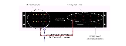
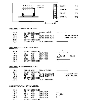
The FaxPress’ DID converter interface on the front panel’s left side has four matched input and output pairs. These pairs of RJ11 phone jacks are marked Trunk A/Line A , Trunk B/Line B, etc. These are the four ports of two DID cards.
Each of these matched pairs has:
| ■ | a Lineconnection – uses the eight 4-conductor, straight-through cables Castelle provides. Connects the incoming DID interface’s trunk lines on the left of the FaxPress 7500 to to the fax server interface’s fax lines on the on the right |
The only other connection on the front panel is the 10/100 BaseT network connection. Power is provided to the unit on the backside.
The FaxPress 7500 should be connected to your network, fully operational, and powered on before you connect its DID interface to your DID trunk and the 7500’s fax line interface.
To connect the FaxPress 7500’s DID converter to both your DID trunk and the FaxPress’ fax line interface, follow these steps:
| 1. | Connect the four 6-conductor, cross-wired cables provided to the FaxPress DID interface’s four RJ11 phone jacks, marked Trunk A, Trunk B, Trunk C, and Trunk D. |
| 2. | Connect the other ends of the four 6-conductor, cross-wired cables to your DID trunk. Make sure pin 1of the RJ11 plug of the cable connects to pin 1 of the RJ11 plug on the end of the cable, pin 2 connects to pin 2, etc. The DID interface is sensitive to the tip and ring polarities on the DID trunk line, and requires the tip signal on pin 3 of the RJ11 phone jack and ring on pin 4. |
Sometimes, when the phone company installs the DID trunk line, the tip and ring polarities are not configured to follow the correct pin outs. For this reason, the tip and ring pin outs of the wall’s phone jack might not meet the FaxPress 7500-DID’s requirements.
| 4. | Connect the other ends of the four phone cables to the first four of the eight RJ11 phone jacks marked Line 1, 2, 3, 4 on the front panel’s right side, i.e., the FaxPress’ fax server interface. |
| 5. | Connect one end of the remaining four phone cables to the fax server interface’s phone jacks marked Line 5,6,7 and 8, and the other to the phone lines your company will use for outgoing faxes. |
| 6. | Reset the FaxPress 7500 using the power switch on the back of the unit. Next, you must configure the FaxPress 7500’s server software according to the steps described in Configuring the FaxPress 7500’s Server Software. |
During the initial call after the system is powered up, the FaxPress DID’s auto DID feature will detect the given DID trunk parameters – i.e., whether the trunk uses wink-start or immediate-start mode, dial pulse digits or DTMF digits, as well as the number of incoming DID digits – then memorize and match them to the appropriate DID interface.
DID Setup Tips
Use this information to help resolve any connectivity issues.
| ■ | DID is polarity sensitive. Connect Tip to Tip Ring to Ring. |
tiP = Positive = Ground Potential.
riNg = Negative = -48 volts.
| ■ | If your DID trunks return a busy signal, try reversing tip and ring. If the DID trunk continues to return a busy signal, try checking call traffic because available DID trunks may be in use. |
| ■ | Most DID issues are wiring related. The FaxPress 7500 DID’s built-in Exacom DID converter is made by CTPX. Call CTPX at 1-651-293-0535 for tips, help or troubleshooting. |
| ■ | If the DID interface isn’t working, try replacing the 6-conductor, cross-wired phone cable with the 4-conductor, straight-through phone cable. In most cases, this makes the DID interface work. |
| ■ | Try the test procedure in Verifying FaxPress 7500 Function to confirm the FaxPress’ DID converter is functioning properly. |
DID & CTPX Interface Technical Data
The DID trunk provided by your phone company must meet the following specifications to be used with the FaxPress.
Installing the FaxPress 7500 E&M
Using the FaxPress 7500 E&M with your E&M trunk will require both hardware setup,described in the following Before You Begin and Connecting the FaxPress 7500 E&M to your E&M PBX sections, as well as FaxPress server software configuration, described inConfiguring the FaxPress 7500’s Server Software.
The FaxPress 7500 E&M allows E&M compatible PBXs to be used with the FaxPress, enabling automatic inbound fax routing. The application of the FaxPress E&M should be limited to an E&M PBX connection. FaxPress 7500 E&M is not intended for connection to the public switched E&M telecommunication network. Per BellCore specifications, E&M Type I interface operation requires a dedicated ground connection between the FaxPress 7500 E&M and the associated E&M equipment.
Before configuring the FaxPress for use with your E&M PBX, please confirm:
| ■ | the FaxPress 8.x server software is installed. (See Installing the Server.) |
| ■ | the FaxPress Client for supervisors is installed. (See Installing FaxPress Clients.) |
| ■ | the FaxPress 7500 can send and receive test faxes through a standard phone line connected to any of the FaxPress’ eight fax lines. |
| ■ | the FaxPress 7500 E&M has a ground loop connection with the E&M PBX. The preferred ground connection for the FaxPress 7500 E&M is a 4-40 screw marked with “GROUND” on the bottom panel of the chassis. |
Also, with regard to your E&M PBX, please make sure:
| ■ | your E&M Trunk/Tie card interface is a two wire, E&M Type I, originate on “E.” Refer to E&M Type I Lead States to confirm. |
| ■ | your E&M Trunk/Tie card is wired properly to interface successfully with the FaxPress’ built-in CTPX VP 200 E&M converter. Refer to the Two Wire E&M Type I Wiring Configuration as you go through the setup steps to confirm. |
| ■ | your PBX is correctly programmed to route incoming calls via the E&M tie card to the FaxPress. If necessary, contact your PBX manufacturer to confirm. |
| ■ | you know whether your E&M PBX is passing 3 or 4 digits to the FaxPress’ E&M converter. The FaxPress offers an Enabling DID receiving diagnostic mode utility for determining the number of digits being sent. If the signal contains more than 3 or 4 digits, research the programming of the PBX to determine if the extra digits can be removed. |
Connecting the FaxPress 7500 E&M to your E&M PBX
The FaxPress’ E&M converter interface on the front panel’s left side has four matched input and output pairs. These pairs of RJ11 phone jacks are marked Trunk A/Line A , Trunk B/Line B, etc. Each of the sets has:
| ■ | a Line connection – uses the eight 4-conductor, straight-through cables Castelle provides. Connects the incoming E&M interface’s trunk lines on the left of the FaxPress 7500 to to the fax server interface’s fax lines on the on the right |
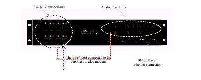
The E&M converter provides four E&M trunk line interfaces. Four 6-position phone modular connectors marked as TRUNK A, TRUNK B, TRUNK C, and TRUNK D are provided on the front panel and four phone line cables are provided for the E&M trunk/tie card connections. These four phone line cables are 6-conductors, cross-wired, which means pin 1of the phone plug of the cable connects to pin 1 of the plug on the end of the cable, pin 2 connects to pin 2, etc.
The 10/100 BaseT network connection is also located on the front panel. Power is provided to the unit on the backside.
To attach the FaxPress 7500’s E&M converter to your E&M PBX and the FaxPress’ fax line interface, follow these steps:
| 1. | Connect the four 6-conductor, cross-wired cables provided to the FaxPress E&M interface’s four RJ11 phone jacks, marked Trunk A, Trunk B, Trunk C, and Trunk D. |
| 2. | Connect the other ends of the four 6-conductor, cross-wired cables to your E&M trunk/tie card. Connect E to E, M to M Tip to Tip and Ring to Ring. |
| 4. | Connect the other ends of the four phone cables to the first four of the eight RJ11 phone jacks marked Line 1, 2, 3, 4 on the front panel’s right side, i.e., the FaxPress’ fax server interface. |
| 5. | Connect one end of the remaining four phone cables to the fax server interface’s phone jacks marked Line 5,6,7 and 8, and the other to the phone lines your company will use for outgoing faxes. |
| 6. | Reset the FaxPress 7500 using the power switch on the back of the unit. |
| 7. | Next, you must configure the FaxPress 7500’s server software according to the steps described in Configuring the FaxPress 7500’s Server Software. |
After the E&M trunks are connected and powered the FaxPress 7500 E&M is ready to process and convert calls.
E&M Setup Tips
Use this information to help resolve any connectivity issues.
| ■ | Make sure that the type of E&M trunk/tie card you’re using is E&M 2-wire, Type 1, and confirm that switch originates on “M”. |
| ■ | Confirm grounding. |
| ■ | Most E&M issues are wiring related. The FaxPress 7500 E&M’s built-in VP200 E&M converter is made by CTPX. Call CTPX at 1-651-293-0535 for tips, help or troubleshooting. |
| ■ | Try the test procedure in Verifying FaxPress 7500 Function to confirm the FaxPress’E&M converter is functioning properly. |
Use the E&M type I lead state information to determine E&M trunk/tie card status.
| ■ | E&M trunk/tie card supervision from the PBX to the FaxPress 7500 E&M is via the “M” lead. |
| ■ | E&M trunk/tie card supervision from the FaxPress 7500 E&M to the PBX is via the “E” lead. |
| ■ | The E&M trunk/tie card to the FaxPress 7500 E&M is in idle condition when the “M” lead is at ground potential. |
| ■ | The E&M trunk/tie card to the FaxPress 7500 E&M is in seized condition when the “M” lead is in battery potential. |
| ■ | The E&M trunk/tie card is in idle condition when the “E” lead is open. |
| ■ | The E&M trunk/tie card is in seized condition when the “E” lead is at ground. |
|
E&M Type 1 Lead States |
|||
| Idle | Active | Lead | |
| From switch to FP7500-E&M |
Ground |
Battery | M |
|
To switch from FP7500-E&M |
Open |
Ground | E |
Two Wire E&M Type I Wiring Configuration
The figure below shows you the wiring configuration on both the E&M trunk/tie card end and on the FaxPress E&M converter end. The FaxPress’ built-in E&M converter is a CTPX VP200, a two wire, E&M Type I, originate on “E.
Configuring the FaxPress 7500’s Server Software
FaxPress 7500 DID and FaxPress 7500 E&M require identical FaxPress 8.x server software configuration. The FaxPress must be configured to recognize automatic inbound routing is being used for the fax lines connected to the FaxPress’ DID or E&M interface, and not try to use those fax lines for outbound faxes.
The PBX must also be configured to route incoming calls to the FaxPress and transmit only the 3 or 4 digits associated with the FaxPress mailboxes, and no other digits. For specific PBX configuration help, refer to your PBX documentation.
Follow these steps to configure your FaxPress 7500 DID or E&M for automatic inbound routing:
| 1. | Log onto FaxPress with supervisor privileges. (Start>Programs>FaxPress>FaxPress) |
| 2. | Go to FaxPress's Main menu, select the fax server you are configuring for DID, then right-click on the server name and left-click on Properties. |
| 3. | Select the Line Settings tab. |
| 4. | From the Fax Line drop down menu, choose the line connected to the FaxPress’ DID or E&M converter interface. |
| 6. | Select the Advanced Functions tab. Check the I am using DID for inbound fax routing box, even if you’re using a 7500 E&M. Make sure the correct radio button is selected in the Change Number of digits for DID trunk line field. Most systems will be set for 4 digits but some may call for 3 digits only. |
| 7. | Click OK to exit the FaxPress Properties and return to FaxPress. Next, you’ll configure FaxPress mailboxes with Mailbox IDs. |
The To enable DID receiving diagnostic mode option is a troubleshooting aid. See FaxPress 7500 Issues and Solutions for more information on using this feature.
To receive faxes through DID or E&M inbound routing, FaxPress mailboxes must be assigned mailbox IDs that associate them with their DID trunk or PBX phone numbers. All mailbox IDs must consist of either three or four digits, depending on how many digits the phone company, or your PBX, is passing to the FaxPress.
Follow these steps to associate a FaxPress mailbox with one of the DID trunk or PBX E&M tie card phone numbers:
| 1. | Log onto FaxPress with supervisor privileges. (Start>Programs>FaxPress>FaxPress) |
| 2. | Expand the Administration branch, then click on Users. |
| 3. | Select a user from the list of users on the right. |
| 4. | Right-click on the user, then left click on Properties to bring up the User Properties screen. |
| 5. | Enter the last 3 or 4 digits of the users PBX/DID number in the Mailbox ID field. If the phone company is passing along the last 3 digits, enter the last 3 digits of the phone number in the box. If the phone company is passing along the last 4 digits, enter the last 4 digits of the phone number in the box. |
| 6. | Click OK to save and close. |
If a fax is sent to a phone number for which there is no corresponding FaxPress mailbox, FaxPress will, by default, reject the incoming fax.
In FaxPress 6.3 and above you may configure the FaxPress server to accept faxes sent to a phone number without a corresponding FaxPress mailbox. The received faxes will be stored in the FaxPress Unaddressed mailbox.
To configure the FaxPress server to accept incoming faxes sent to phone numbers without FaxPress mailboxes, follow these steps:
| 1. | Open the Castelle System folder on your hard drive. The number of fxcfg files in the System folder correspond to the number of fax lines. |
| 2. | Double-click on an fxcfg file to bring up the notepad file. Type: |
did_failure=1
as shown in the example below to allow incoming faxes sent to DID numbers without corresponding FaxPress mailboxes to be received and stored in the FaxPress Unaddressed mailbox.
Conversely, type:
did_failure=0
to reject incoming faxes sent to numbers with no corresponding FaxPress mailboxes.
To specify the number of seconds the FaxPress should allow for incoming digit reception. The timeout range is 1 to 15 seconds. The default value is 15 seconds.
To customize the timeout interval, type:
did_timeout=9
Verifying FaxPress 7500 Function
To verify that your FaxPress 7500 DID or E&M, and its built-in DID or E&M converter are functioning properly, follow these steps:
| 1. | Temporarily configure FaxPress with Line 1 set for Input only and DID and Line 5 set for Output only. |
| 2. | Confirm at least two FaxPress users are configured for DID use. That is, make sure each user is assigned a mailbox ID. |
| 3. | Using FaxPress, send a test fax to one of the DID-configured FaxPress users. Use only the 3 or 4 digit mailbox ID to send the test fax. |
| 4. | You should hear Line 5 call in through the Trunk and come out the Line-to-Line 1 on the front panel. |
| 5. | You should hear a clicking noise inside the 7500 which is the line ringing. |
| 6. | The line will be picked up and the fax will be sent to the recipient’s mailbox. |
If the above process works, and the test fax is received, the FaxPress 7500 is functioning properly. Any problems your users may have sending or receiving faxes to other recipients indicates a phone company issue with the DID Trunks or, in the case of the FaxPress 7500 E&M, a possible PBX or tie card issue.
FaxPress 7500 Issues and Solutions
The following information is intended to provide solutions for common 7500 routing issues. For more detailed information about routing or DID integration, please refer to the automatic routing technical notes Castelle provides.
Issue: The FaxPress is receiving incoming faxes but they do not go to any of the individual fax boxes
Your phone equipment must actually be sending the same number of DTMF digits as you have configured the FaxPress to receive, typically three or four digits. Castelle provides an Enable DID receiving diagnostic mode utility to confirm that the correct number of DTMF digits are, in fact, being sent.
To use this diagnostic mode utility, follow these steps:
| 1. | Log onto FaxPress with supervisor privileges. (Start>Programs>FaxPress>FaxPress) |
| 2. | Go to FaxPress's Main menu, select the fax server you are configuring for DID, then right-click on the server name and left-click on Properties. |
| 3. | Scroll over to and select the Advanced Functions tab. |
| 4. | Check the box next to Enable DID receiving diagnostic mode. |
| 5. | Click OK. You’ll be prompted to reboot the workstation. |
| 6. | A dtmf.log file will now be created in the Castelle\serial number\fxdiag directory. Once you have rebooted the FaxPress server, the dtmf.log file should start to capture the digits being sent through the CTPX cards to the FaxPress. |
View the log file from a command prompt by changing directories to:
Castelle\serial number\fxdiag
If the dtmf.log does not begin capturing digits, take the line connected to the trunk in question and disconnect it from the Line on the right side of the 7500.
Connect a standard household (analog) phone to the first line going from the PBX to the FaxPress. Call a DID number and pick up the phone’s handset when it rings. Listen to make sure you hear only the correct number of digits being sent by the PBX.
Your phone system may be set up to add digits to the front or end of the numbers sent to the FaxPress. It is imperative that the phone system not send these touch tones. By listening, you can tell if they are being added. If so, research the programming of the PBX to determine if these digits can be removed.
Issue: FaxPress cannot send outgoing faxes
Make sure there are dial tones on all connections between the PBX and FaxPress. Also, test to see if dialing “9” breaks the internal dial tone and connects you to the phone company’s dial tone. If so, make sure that the FaxPress is configured to dial “9,” first before sending any outbound faxes.
The FaxPress 7500’s interface LEDs are identical for both the FaxPress 7500 DID and the FaxPress 7500 E&M.
Refer to these for equipment and operations status.
|
DID Interface LEDs |
||
|
DID Line |
LED | Indicates |
|
A |
TRUNK A is waiting for a new call | |
| TRUNK A is seized (in off-hook state) | ||
| LINE A is seized (in off-hook state) | ||
|
B |
Green LED on |
TRUNK B is waiting for a new call |
|
Red LED on |
TRUNK B is seized (in off-hook state) | |
|
Yellow LED on |
LINE B is seized (in off-hook state) | |
|
C |
Green LED on |
TRUNK C is waiting for a new call |
|
Red LED on |
TRUNK C is seized (in off-hook state) | |
|
Yellow LED on |
LINE C is seized (in off-hook state) | |
|
D |
Green LED on |
TRUNK D is waiting for a new call |
|
Red LED on |
TRUNK D is seized (in off-hook state) | |
|
Yellow LED on |
LINE D is seized (in off-hook state) | |
The FaxPress 7500’s fax server LEDs are identical for both the FaxPress 7500 DID and the FaxPress 7500 E&M.
Refer to these LEDs for fax server operations status.
|
LED |
Indicates |
|
LINE 1 Red LED on |
LINE 1 is seized |
|
LINE 2 Red LED on |
LINE 2 is seized |
|
LINE 3 Red LED on |
LINE 3 is seized |
|
LINE 4 Red LED on |
LINE 4 is seized |
|
LINE 5 Red LED on |
LINE 5 is seized |
|
LINE 6 Red LED on |
LINE 6 is seized |
|
LINE 7 Red LED on |
LINE 7 is seized |
|
LINE 8 Red LED on |
LINE 8 is seized |
|
100BT LED on |
100 Base-T network is linked. |
|
10BT LED on |
10 Base-T network is linked. |
|
DATA LED on |
Network activity. |
|
ALERT LED on |
Uninterrrupted, indicates the system is in an alert condition. The ALERT LED may blink during the power up boot sequence. |
|
READY LED on |
This LED should be continuously on showing the system is in normal running mode. It may blink during the power up boot sequence. |
Technical Data, FCC and Safety Information
|
FaxPress 7500 Technical Data |
||
|
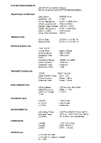
Telephone Interface |
Impedance |
600/900 Ohm |
|
Insertion Loss |
< 3dB | |
|
Trunk Resistance |
0 Ohm to 1800 Ohm | |
|
Trunk Loop Current |
16mA to 60mA | |
|
Battery Feed Voltage |
-48VDC, +/-10% | |
|
TRUNK Resistance |
0 Ohm to 400 Ohm | |
|
Wink Duration |
248ms nom. | |
|
Hook Flash Duration |
500ms | |
|
Termination |
Trunk Side |
4x RJ-11 for DID, 2 x 6 position 6 pin modular for E&M |
|
Line Side |
4xRJ-11 | |
|
Receive Signaling |
Dial Pulse |
|
|
Pulse Rate |
8pps to 20pps | |
|
Percent Break |
32% to 80% | |
|
Interdigit Time |
150ms min | |
|
DTMF |
||
|
Sensitivity Range |
-25dBm to +3dBm | |
|
Tone Duration |
40ms min | |
|
Interdigit Time |
40ms min | |
|
Maximum Twist |
10dB | |
|
Transmit Signaling |
DTMF |
FAST / SLOW |
|
Digit Transfer Delay |
0.5s/1.0s | |
|
Tone Duration |
50ms/100ms | |
|
Interdigit Time |
50ms/100ms | |
|
Ring Generation |
Ring Voltage |
70Vrms max. @no load |
|
Ring Frequency |
58Hz, +/-10% | |
|
Maximum Ringer Load |
1.5REN | |
|
Environmental |
Operating Temperature |
+32F to +104F (OC to +40 C) |
|
Storage Temperature |
-40F to +185 F (-40C to +85 C) | |
|
Humidity |
5% to 95%, non condensing | |
|
Dimensions |
Length |
16.73” |
|
Height |
3.47” | |
|
Depth |
14” | |
|
Approvals |
FCC part 68 |
|
|
FCC part 15, class A |
||
|
UL |
||
|
Power Supply |
50Hz/60Hz 90VAC-250VAC auto-ranging |
|
FCC Part 68 Information
This equipment complies with Part 68 of the FCC Rules. The FCC Part 68 Label is located on the back of the unit’s case. This label contains the FCC Registration Number for this equipment. If requested, this information must be provided to your telephone company.
Connection to the telephone network should be made by using standard modular telephone jacks, type RJ-11C.
The plugs and/or jacks used must comply with FCC Part 68 rules.
|
System Port Identification Facility Interface & Service Order Codes |
||||
|
Port Identifier |
Facilities Interface Code | Service Order Code | Network Jacks | REN/AS |
|
Line 1 - 8 |
02LS2 | 9.ON | RJ11C | 0.4A |
| DID Port 1 - 8 | 02RV2-T | 6.ON | RJ11C | AS.2 |
If this telephone equipment compromises the telephone network, the telephone company will notify you in advance of any temporary suspension of service that might be required. If advance notice isn’t practical, however, the telephone company reserves the right to notify the customer as soon as possible. You will also be advised of your right to file a complaint with the FCC if you believe it is necessary.
The telephone company may make changes in its facilities, equipment, operations or procedures that could affect the proper functioning of your equipment. If so, you’ll be notified in advance to modify your system to accommodate the changes. Advance modifications should allow for uninterrupted service.
DO NOT DISASSEMBLE THIS EQUIPMENT. It does not contain any user serviceable components.
Direct Inward Dialing (DID)
Allowing this equipment to be operated without providing for proper answer supervision is a violation of Part 68 of the FCC rules.
Proper supervision is provided when:
| 1. | This equipment returns answer supervision to the PSTN when DID calls are: |
| ■ | answered by the called station |
| ■ | answered by the attendant |
| ■ | routed to a recorded announcement that can be administered by the CPE user |
| ■ | routed to a dial prompt. |
| 2. | This equipment returns answer supervision on all DID calls forwarded to the PTSN. Permissible exceptions are: |
| ■ | a call is unanswered |
| ■ | a busy tone is received |
| ■ | a reorder tone is received |
E&M
FaxPress 7500-E&M must not be connected to the Public Telephone Network. The FaxPress 7500 E&M is not FCC Part 68 registered for connection to the Telephone Company Network.
FCC Statement
This device complies with the limits for a Class A digital device, pursuant to Part 15 of the FCC Rules. Operation is subject to the following two conditions:
This device may not cause harmful interference.
This device must accept any interference received, including interference that may cause undesired operation.
Electrical Safety Advisory
Castelle recommends the installation of an AC surge arrestor in the AC outlet used with this equipment. Telephone companies report that electrical surges, typically lighting transients, are very destructive to customer terminal equipment connected to AC power sources.
Safety Information
Voltage
The Castelle FaxPress 7500 operates only from a 90-250 volt, 60/50 Hz AC source. Do not connect to any other power source.
Power Source
The FaxPress 7500 operates from a single-phase power source. Operation from power sources where both current-carrying conductors are live with respect to ground (e.g. phase-to-phase on a 3-wire system) is not recommended.
Proper AC source grounding, and grounding circuit continuity are vital for safe operation
Power Cord
The FaxPress 7500 comes with a UL listed power cord.
Use only the 3-wire, 3-terminal power cord provided.
To preclude the possibility of electrical shock, do not ever remove the Faxpress 7500 case.
UL Safety Requirement
The FaxPress 7500 product chassis is connected to the earth ground prong of the AC power supply connector for the purpose of safety protection. However, some buildings do not have good earth ground connection to the AC power supply earth ground prong. In order to provide a good protection from electrical shock, it is required to use a cable to tie the product chassis to a known good earth ground of the building. The required contact of the product chassis for the earth ground cable is at a screw (4-40 screw size) marked as “GROUND” on the bottom panel of the chassis.
|
FaxPress WebHelp
Last Updated: 9/12/2007
E-mail this page |
Castelle 855 Jarvis Drive, Suite 100 Morgan Hill, CA 95037 Toll-free 800.289.7555 Tel 408.852.8000 Fax 408.852.8100 |